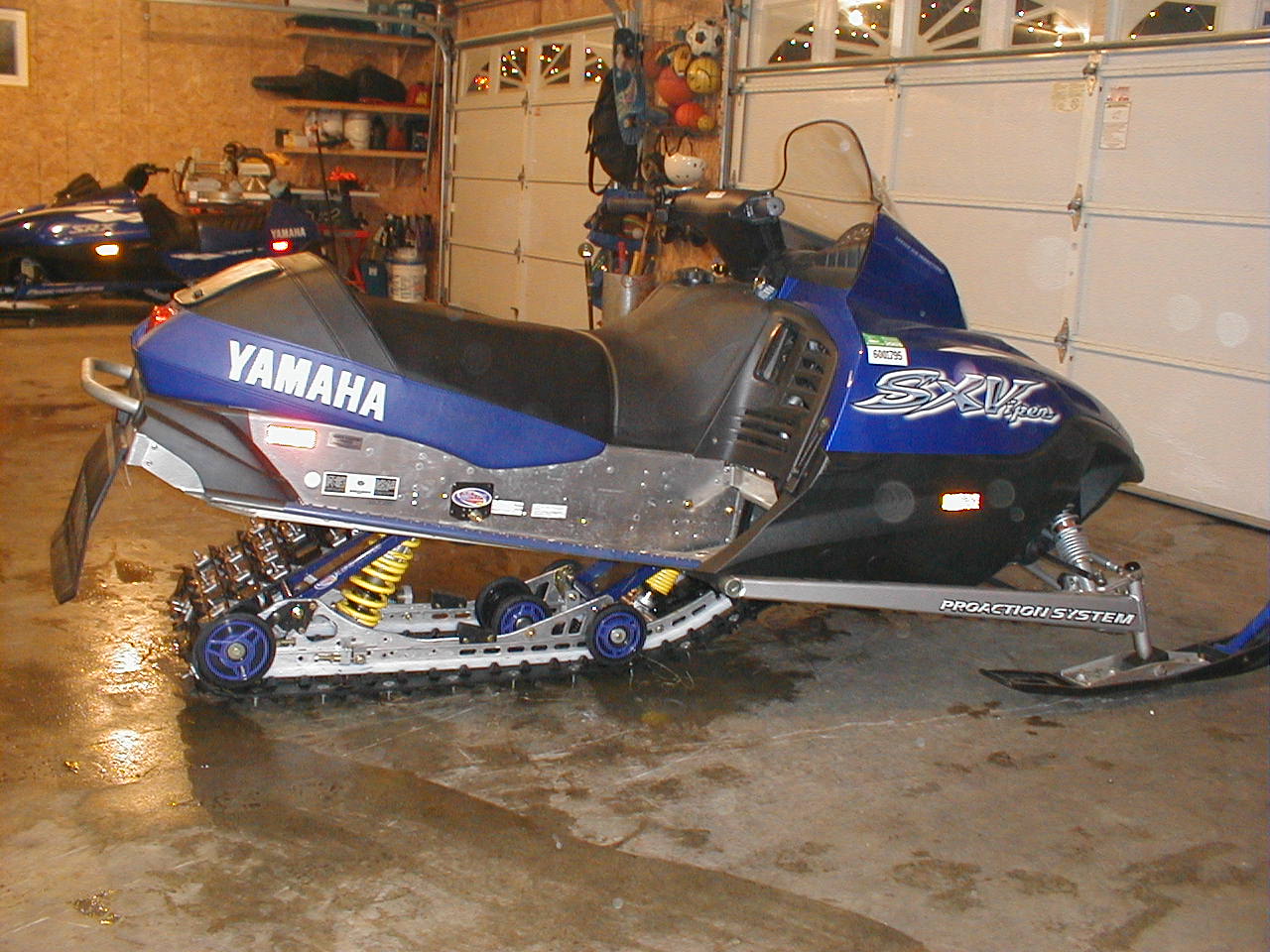
Totallyamaha Pro-Action M10 Install
|
|
|
|
|
|
Before beginning the installation, Totallyamaha recommends that you thoroughly read the installation package provided with your M-10, Be sure you understand all of the layout procedures described. Take your time with the layout, it is very critical that your new suspension be mounted parallel to the tunnel and perpendicular to the drive shaft. (If any of the information provided below conflicts with the installation package provided by M10, use the their information) Look through the parts that are provided and make sure you are not missing any mounting hardware.
M10 Tunnel Support Plate Installation:
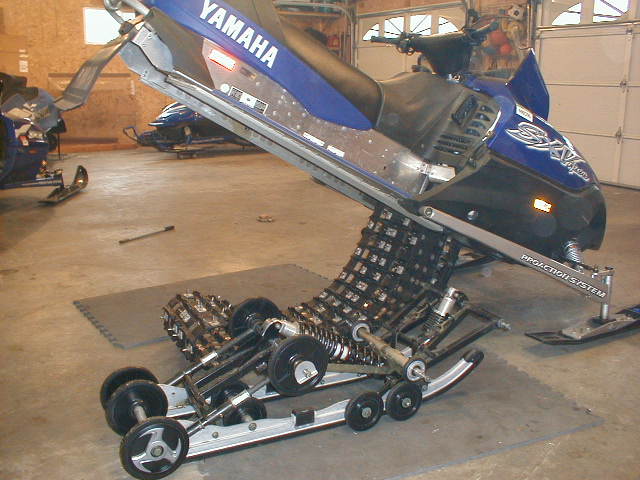
1) Remove your pro-action skid frame by slightly elevate the rear of the sled so the track is about 2" off the ground. Using a 17 mm and 19 mm wrench loosen the rear shaft slightly. Take a 14 mm socket and ratchet and release the track tension. Be sure to count the turns equally off the rear adjusters.
| 2) Raise the sled to a 45 degree angle to ease layout, side template and bracket installation. |
|
Identify the RH side of the sled or mag side by sitting on the sled for reference purposes.
|
|
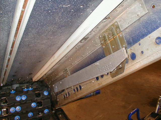
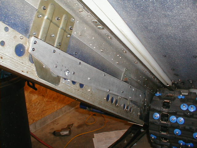
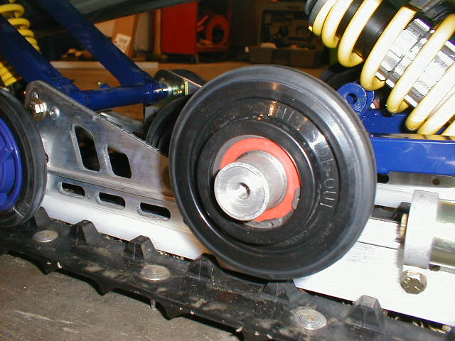
3) Once elevated , roll the track forward under belly pan to make more room to work. Remove existing front torque arm mount plates on the inside of tunnel. See picture to left. These are the front most brackets (triangular shape) nearest the drive shaft . |
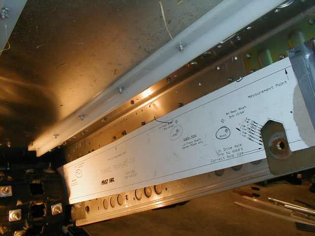
4) With a caliper or venire, measure across the flats of the drive axle on the RH side. According to our figures this measurement should be 1.062". Also do the same on the collar on the LH side. This figures should measure 1.390".
|
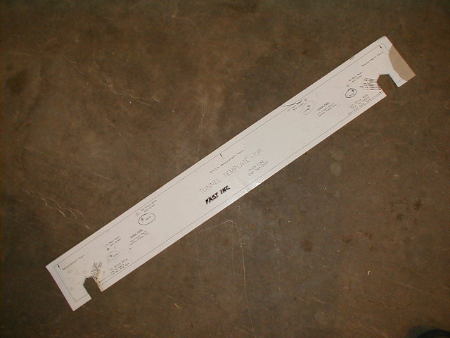
5. Using the template provided & Diagram 1, identify the set of lines that is closest to the RH shaft diameter (or across flats measurement). Using a ruler, pencil, scissors and printed lines (as guides), layout and trim the template to the spec. we determined, approx. 1/64” (.5mm) smaller than shaft dimension (snug fit will hold the template. in position better).** Repeat this for the LH Collar and cut out template accordingly. |
|
6. Be sure to rotate Hexagon Points of the shaft in a vertical position, see Diagram 1. Using care, slide RH Drive Axle Slot over axle. Note: Slot must slide over flats of hex or over round shaft. It will not slide over the points of the hex shaft. **
Diagram 1 **
|
|
7. Rotate drive axle and
Template. to a
position absolutely parallel with top inside of tunnel, see Diagram 1 above. Check to be
certain the slot is touching the top of the drive axle, see Diagram1 . Be certain
to adjust measurements for height variations due to short corner braces, cut
outs, etc. Note: Accuracy is important in finding parallel location of template. This process locates the M-10. Record measurements for comparison with opposite side later. Measurement should be approximately equal. Once you have located template., it’s best to clamp or duct tape into position.** |
8. Check for these markings on
template.: RH
Rear Rivet, RH Front Rivet, Check Point, RH Front shaft. Center punch these
points only, through template. Follow up punch mark only, by lightly spotting each with a small
(1/16”) drill bit. Next, drill only the RH Front Rivet and RH Rear Rivet using a
3/16” bit through Template. & tunnel, then remove template. ** You should
have only made 2 punch marks and finally 2 holes to assist you in holding the
TSP.
| 9. Position the Tunnel Support Plate’s to the inside of the tunnel. Locate rivet hole on upper front edge of Tunnel Support Plates & insert screw provided, see Drawing above. Temporarily screw into RH Front Rivet hole, drilled earlier in tunnel. On upper edge of Tunnel Supports Plate., locate the 3rd rivet from rear & insert screw provided, see Drawing above. Temporarily screw into RH Rear Rivet hole, drilled earlier in tunnel. ** |
|
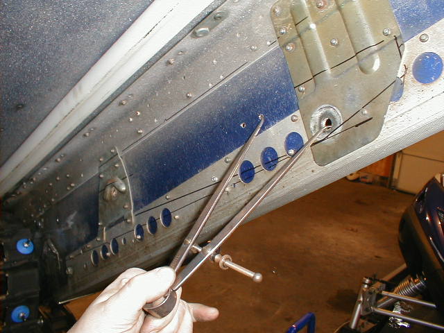 |
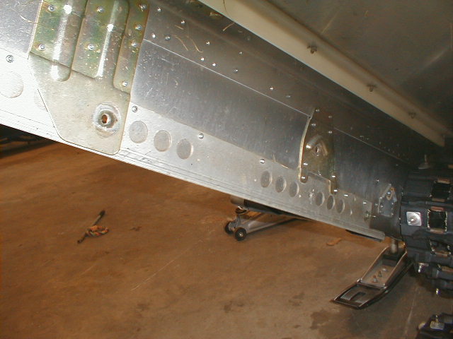
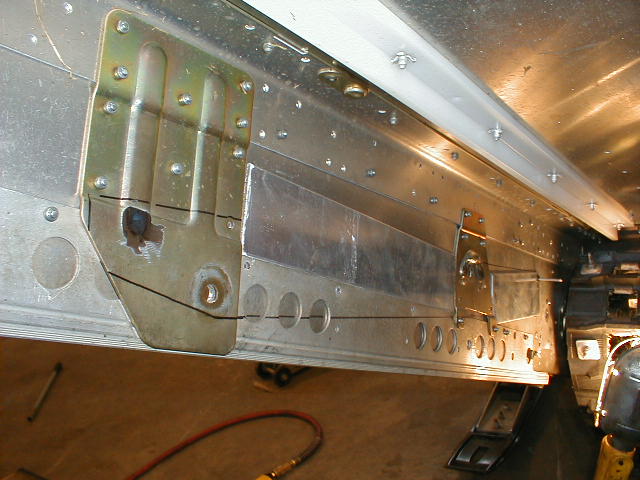
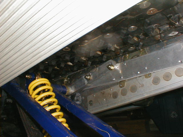
10. Use scribe or marker to trace
Tunnel Support Plate on tunnel. Take note to existing reinforcements, decide which ribs or rivets need to be removed/ground
down to allow Tunnel Support Plate. to lay flat on tunnel. See picture at left
for areas needing grinding. ** Helpful hint: We used dividers to verify hole locations from the common rear holes to rivet transfer holes as shown in the left picture. This helped us reassure that both Tunnel Support Plates are mounted in the same place on each side. |
| 11. Use a small grinder or drill to remove existing ribs & rivets as noted above. Then relocate Tunnel Support Plates on the tunnel & install the small screws provided in RH Front & Rear(ward) Rivet holes. ** |
|
|
|
12. Verify Front Shaft Location at RH Checkpoint (centerpunched into chassis in
Step 8). Partially insert (don’t drill yet) two 3/8” bolts into the standard
holes (by dimples) in the RH Torque Arm Bracket and Tunnel Support Plate., see
left Diagram ** Note:The RH Checkpoint mark must appear in the center of the 7/16” hole in Torque Arm Bracket. If not then re-check previous steps locating Template.** |
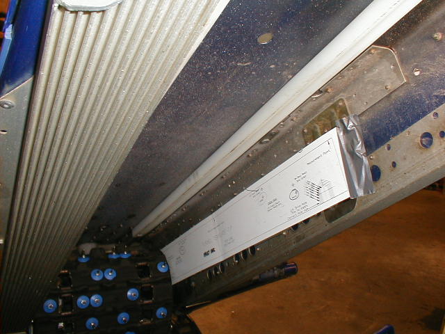
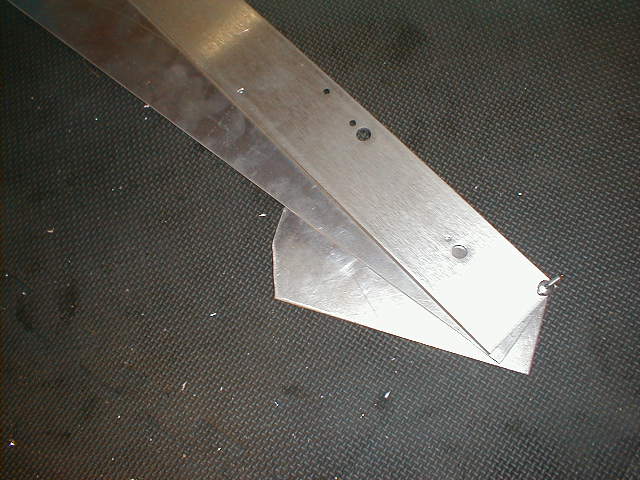
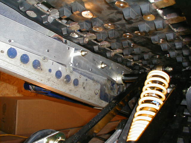
| Note: Now it is time to fit the Shim Stock, which will evens up tunnel with the existing reinforcement bracket. See picture right for shim stock. You may have to add more shim stock to the tunnel side under the TSP to get them flush and parallel from right to left. It may help to measure you final inside dimension to the supplied cross shafts. The shafts should be slightly smaller approx. 1/8" |
|
|
|
13.Remove the front sheet metal screw from
the Tunnel Support Plate and slide the Front Shim under it so that the 3/16" hole lines up in
between the Support Plate & tunnel, reinsert screw.** Next do the same for the
rear Shim
so that the 3/16" holes lines up in between the Support Plate & tunnel
and
reinsert screw. ** Note If the any
of the Shims overhang any existing
reinforcements, mark and trim the Shim. Next reinstall Shim under the Support
Plate and
rivet it from the outside into position. Repeat this process for both
Tunnel Support Plates LH and RH. |
14. At front of the Tunnel Support Plate, drill the two 3/8” bolt holes in tunnel for the Front Torque Arm Brackets.
| 15. As noted in Brand
Spec chart to the right, the initial recommended Rear Torque
Arm hole is A, this hole will fit all chassis. If the chassis is deep enough the
B hole may be used for more tunnel clearance. Large riders (above 250 lb.) can
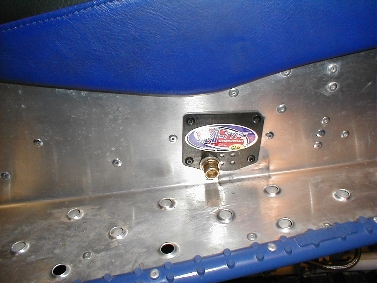
use C or D to increase their adjustable load capacity. ** Note: Lower holes B & D may require some grinding on the lower edge of the Outside Rear Tunnel Plates for proper fit.** 16. Once the hole is selected, from inside the tunnel, position the Outside Rear Tunnel Plates against Tunnel Support Plate. and select the matching set of 3/16” holes to drill through tunnel. Be certain rivets reach at least an 1/8” through all layers and rivet Outside Rear Tunnel Plates to tunnel.** 17. Referring back to the hole location chosen in step 15 (from the inside tunnel), drill hole out to 7/16”. Apply M-10 decal to Outside Rear Tunnel Plates.** |
|
16. Finish drilling the 3/16” rivet holes
through the Support Plates and Tunnel. Complete the riveting of the Tunnel
Support Plates and shim stock to the tunnel. Be
certain all rivets reach through all materials by at least 1/8”. ** You are now
ready to install the M10......WOW.
M10 Installtion:
1. If your M-10 comes with a 90 degree grease fitting included with mounting hardware, install grease fitting in the upper front torque arm. It is easiest greasing with fitting facing to left side. **
|
|
2. Disconnect both front and rear upper shock mounts front the M-10 suspension system (if not done). This will ease installation. ** |
| 2a. Check the Brand Spec Sheet for different location on Front Torque Arm on the rail. Re torque to 35 ft.lbs. if needed. ** |
|
|
|
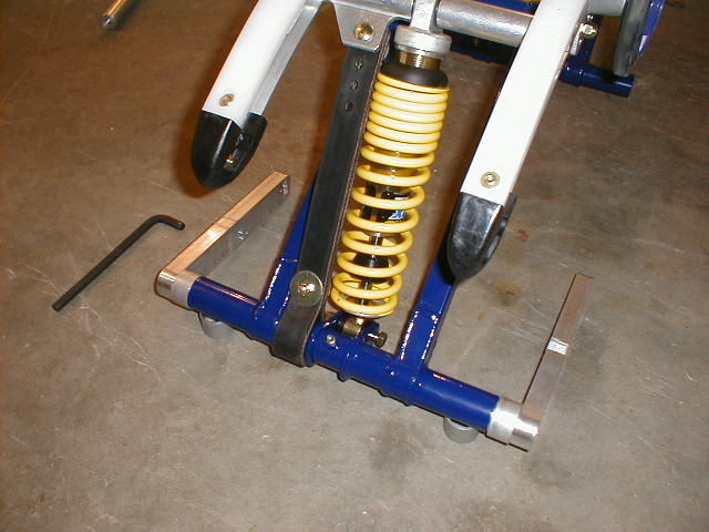
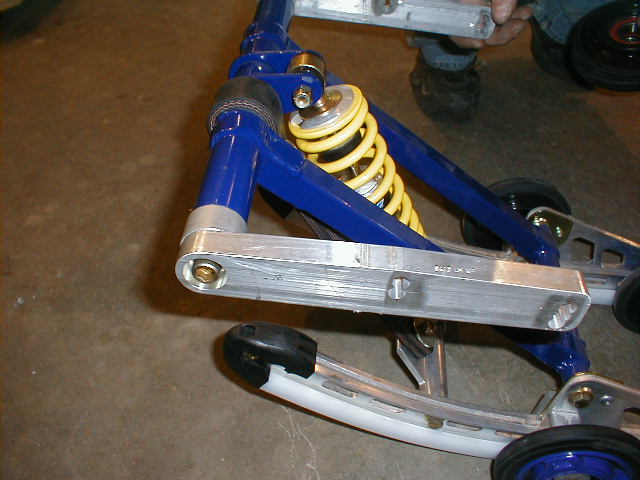
3. Slide both front and rear upper cross shaft through the swing arms. The front shaft is the same size throughout. The rear shaft has machined ends. Install the two torque arm brackets (Stamped RH, LH) and spacers on the front torque arm. Install the 7/16 x 1 1/4” bolts, 7/16” lock washer, so they are concealed (recessed) in the brackets. Note: The torque arm brackets must be parallel to each other. This can be accomplished by swinging the front torque arm forward to the floor and then tighten the bolts in the torque arm brackets while hold the brackets flat to the floor. (See Drawing 6.) Use red loctite #271 on the bolt threads and torque to 40 ft.lbs.** |
| 4. Installing upper idler wheels and spacer on the top cross shaft of the rear arm. Make certain the labeling on the idlers wheel dictates position. (This Side Out) |
|
|
|
5. Install M-10 suspension in tunnel. Fold front are forward and rear arm towards center of suspension. Insert rear of suspension in to track then slide the front into position. |
| 6.
Use holes with DIMPLE mark on Torque Arm Brackets, (see Drawing 5). Install
3/8 x 2 1/2” bolt & 3/8” washer through rear middle hole & install washer and nut
finger tight. With further adjustment, slide 3/8 x 2 1/2” bolt & washer through
front top hole & install washer and nut on finger tight. Then torque the four
bolts to 30-35 ft. lbs.**
|
|
|
|
7. Lift the rear of suspension into drilled location and thread 7/16 x 1 1/4” Allen bolt with lock washer, flat washer. (Use Loctite #271) Then torque this bolt 40 ft.lbs.** |
| 8. Connect front and rear upper shock mount and torque bolts to 30-35 ft.lbs. Make certain the limiter strap bolt is facing up as supplied. ** |
|
Calibration & Maintenance**
1. Now you are ready to make the crucial step of calibration of suspension .
This procedure is explained step by step in Initial Set-up Reference card and is
thoroughly covered in owners manual. For best results, we recommend that you
read and understand the owners manual which also covers maintenance for the
suspension. .
2. When adjusting limiter strap, place 4-6” block under front of suspension. Do
not use the fifth hole in limber strap if the one you have is equipped with five
adjustment holes.
3. Align and adjust track tension so there is equal spacing side to side. There
should only be 3/4” 19mm gap between rail and track. With machine suspend in air
no weight in track.
4. Check all fasteners torque to proper spec. Grease all four shafts with low
temp grease (Phillips Polytach EP-2 recommended) use four grease zerks fitting
on torque arms.
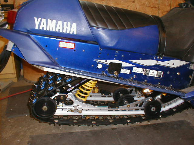
Once the spring preload, spring lengths and sag are adjusted you are ready to ride. Please note: You will have to re-adjust slightly after you have ridden about 50-150 miles as the springs set in. Be careful with this re-adjustment and don’t forget. The M-10 is very forgiving and you may not notice that it has gotten softer but it will become quite easy to bottom out on bigger bumps if you don’t go back and readjust for the spring set in.
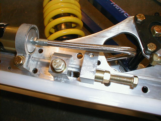
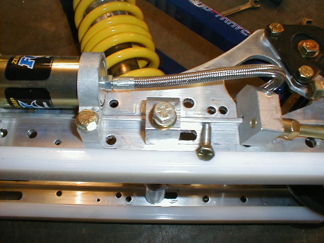
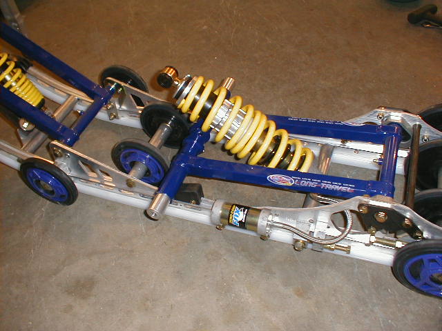
Beyond the initial adjustment you will only have to re-adjust for different riders or riding styles. This is accomplished by simply moving the FRA adjuster or JACK forward or back as shown above. This changes the angularity of your rear shock. The FRA takes about 5-10 minutes to adjust with a couple of wrenches. Whereas, the JACK can be adjusted in less than 30 seconds with a small crank you keep in your storage compartment. The JACK option makes going from an aggressive trail set-up to playing on the lake much easier. You can take out suspension preload for an improved holeshot in less than a minute.
(** Items taken from the Fast Inc M-10 Installation Manual)
Totallyamaha and CCPerformance is not responsible for any damages that these modifications may cause to your vehicle; any modifications are your responsibility if you choose to do so. We are providing information ONLY. Some of these modifications may VOID your warranty and that is your responsibility to look into. The Totallyamaha users have passed along most of the information found on this site. If you have any questions or concerns about anything on this site talk to your dealer before using any of the information. Totallyamaha will not be liable for any damages or personal injury from any modification performed from this site.
Please let us know if you have anything to add to this page to help out other Yamaha owners. For addition to this page Email webmaster@totallyamaha.com
![]()