RX1 Reverse Installation

(Non Pro Action)

NOTE: This kit must be installed by an authorized Yamaha dealer or qualified mechanic to ensure proper function and reliability. Refer to the Service manual for torque specifications and procedures outlined in this manual.
 
Page 1


Preparation for Installation

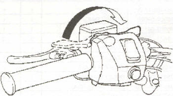
1. Lock parking lever.
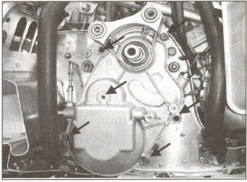
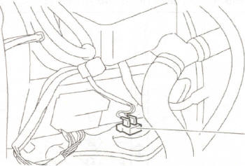
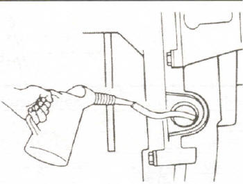
2. Drain gear oiL
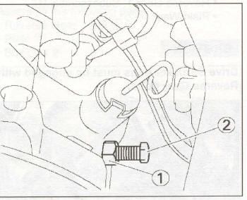
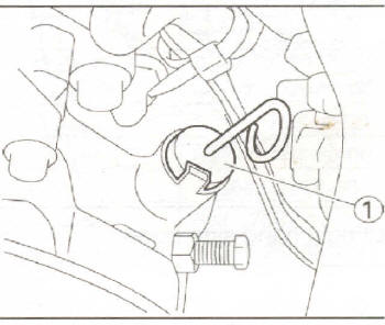
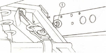
Roll vehicle onto the left side.
Loosen drain bolt (1), Roll vehicle back upright. Place a drain pan beneath the drain bolt. Remove the drain bolt and drain oil. After draining oil, replace the drain bolt.


Preparation of Subassembly
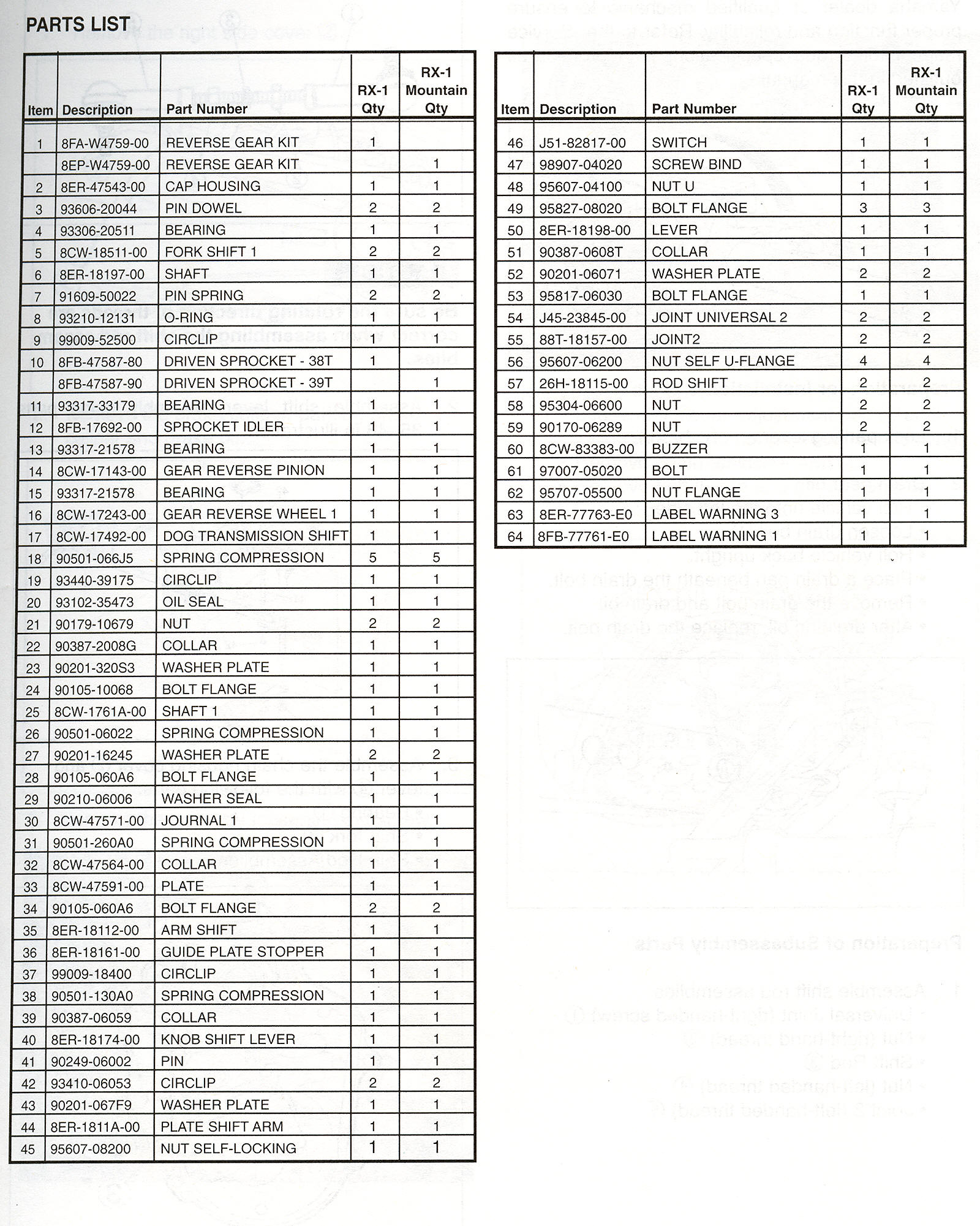
 Parts

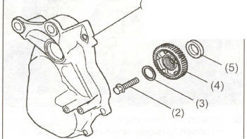
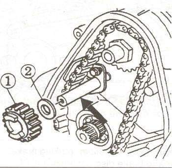
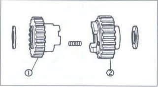
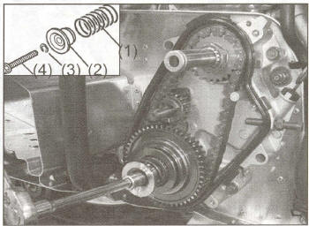
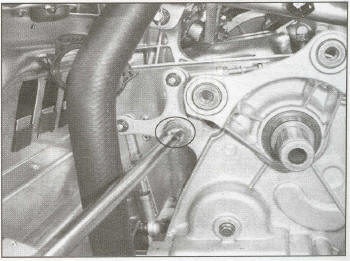
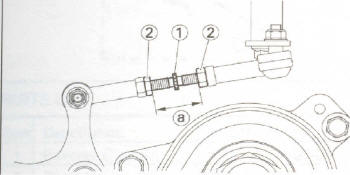
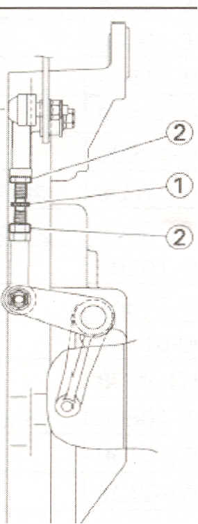
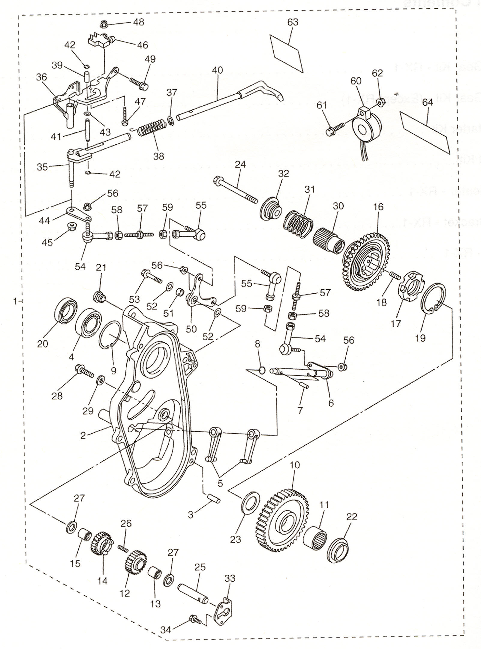
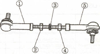
1. Assemble shift rod assemblies
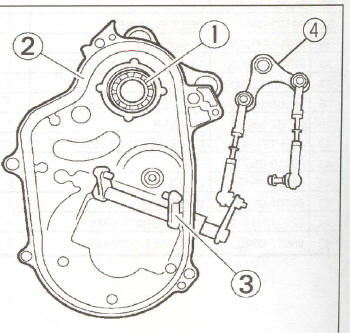
Universal Joint (right-handed screw) (1) . Nut (right-hand thread) (2). Shift Rod (3). Nut (left-handed thread) (4). Joint 2 (left-handed thread) (5)


Caution
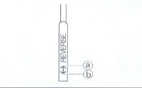
Be sure the rotating direction of threads are correct when assembling the shift rod assemblies.

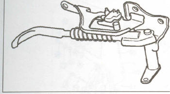
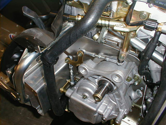
2. Assemble shift lever assembly using parts 35-48 in illustration. This is often pre assembled


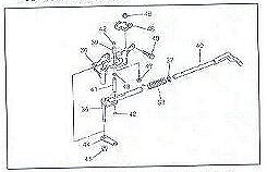
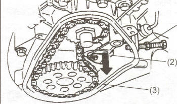
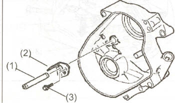
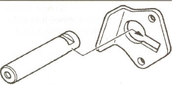
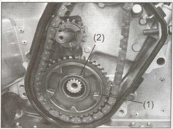
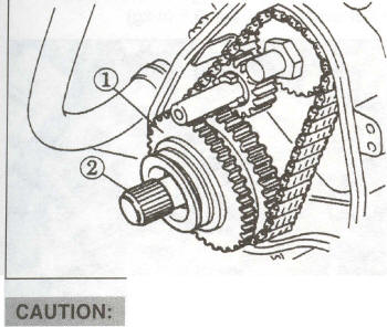
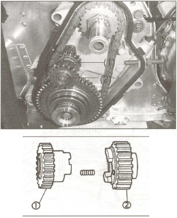
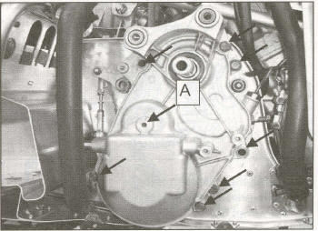
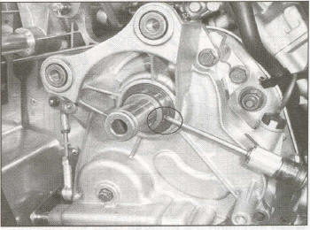
3. Assemble the chain housing cover (2) and lever (4) with the following parts:
Bearing (1), Shift fork (3), Shift Rod Assemblies


Page 2

Removal of Parts

1. Remove
the right side cover (2)


2. Remove the brake caliper, parking brake caliper and brake disc.


3. Remove the collar by loosening set screw.


4. Remove the chain housing cover. Remove bolts


5. Loosen the drive chain.

Loosen tensioner adjustment bolt (1) until inside threads do not protrude into housing. Remove chain tensioner arm (2). Remove bolt flange and driven sprocket (3) along with the collar.


Page 3

6. Parts no longer used:

Housing cover (1), Flange Bolt (2), Washer (3), Driven Sprocket (4), Collar (5)


Reverse Idler Gear Assembly

1. Assemble the following parts:

Reverse Gear Shaft (1), Plate (2), Bolt (3) x 2


NOTE: Place the shaft groove into the cutout on the plate.


2. Install the following parts on the reverse gear shaft:
Plain Washer (2),
Drive Sprocket 2 subassembly (1)
Apply oil at arrow mark.


CAUTION
Be sure that drive sprocket (2) and Reverse Gear (1) are assembled in the correct direction.

3. Install the following parts:
Collar (3) (Refer to next illustration),
Driven Sprocket (1), Plain Washer (2)

Page 4

CAUTION
Make sure the Collar (3) and Driven Sprocket (1) are placed on the correct side.

4. Install the following parts:
Reverse Gear Subassembly (1), Journal (2)


When installing the Reverse Gear Subassembly (1)
its slots must face out.


5. Install the following parts:

Compression Spring (1), Collar (2), Washer (3), Flange Bolt (4)


Torque: 35 ft-Ibs. (4.8 m-kg)


6. Install the following parts:
Compression Spring,
Reverse Gear 1, Subassembly (1), Plain Washer (2)


CAUTION
Drive Sprocket dogs must be engaged with the Reverse Gear dogs.


Page 5

7. Install the following parts:

Chain Tensioner Arm (1)


8. Adjust the chain tension.

Adjustment Steps
Loosen Locknut (1)
, Turn the Adjuster in until finger tight. Tighten Locknut (1)


9. Make sure the two points on the Shift Fork (1) are aligned in the Driven Gear grooves.


10. Install the following parts:
Chain Housing cover, Flange bolt (8mm) 17 ft-Ibs (2.4 m-kg) Flange bolt (10mm) 35 ft-Ibs (4.8 m-kg), Flange bolt -A- (6mm) 7.2 ft-Ibs (1.0 m-kg)


11. Install the Collar with tightened set screw.

Set screw 4.3 ft-Ibs (0.6 m-kg)


12. Tighten the bolt for shift arm

Flange bolt 7.2 ft-Ibs (1.0 m-kg)


Page 6

13. Install shift lever assembly with three mounting bolts. Move shift lever to "FWD" position.


Adjusting Steps

Set lever rod length (a): 27mm . Tighten the locknuts.
Attach shift rod to shift lever.


Turn shift rod (1) to shorten linkage until free play is removed, then turn shift rod back 1/4 turn. Tighten the locknuts.

14. Connect Gear position switch coupler (1)


15. Filling Oil . Fill gear oil.
Oil Type: Yamaha Gear oil
Oil capacity 250cc


Check Oil Level

1. Place the vehicle on level ground.

2. Check the oil level

Check Steps


Remove level gauge CD to clean the gauge point.


Page 7

Install level Gauge (1)
After removing the level Gauge, make sure the oil level is between the upper and lower levels.

(a) Upper level
(b) lower level
 

If below the lower level, add oil.


16. Install the brake disc then the following:
Brake caliper 35 ft-Ibs (4.8 m-kg)
Parking brake caliper 9.4 ft-Ibs (1.3 m-kg)


17. Installation of Back-up Buzzer


18. Install right hand side cover.

Click to Enlarge Parts List

Click to Enlarge Parts List


Totallyamaha is not responsible for any damages that these modifications may cause to your vehicle; any modifications are your responsibility if you choose to do so. We are providing information ONLY. Some of these modifications may VOID your warranty and that is your responsibility to look into. The Totallyamaha users have passed along most of the information found on this site. If you have any questions or concerns about anything on this site talk to your dealer before using any of the information. Totallyamaha will not be liable for any damages or personal injury from any modification performed from this site.